








The design of adjustable steel support falsework systems is a critical step in any concrete construction project. Incorrectly specified or poorly arranged supports can lead to structural failure, concrete distortion, or—worst case—collapse. For structural engineers, project managers, and procurement professionals, a sound understanding of adjustable steel support design principles ensures safe, efficient, and compliant temporary works.
This guide covers the key engineering considerations for designing adjustable steel support systems: load assessment, prop selection, layout design, and compliance with BS EN 1065 and BS EN 12812.
Understanding the Role of Adjustable Steel Support in Falsework
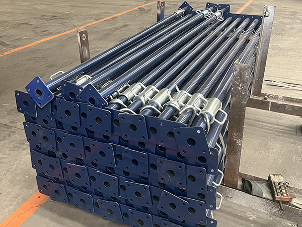
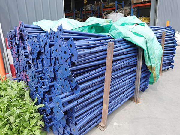
Adjustable steel support—commonly called steel props or acrow props—forms the vertical load-bearing element of a falsework system. They transfer the combined load of formwork, freshly placed concrete, and construction traffic to the ground or existing structural floor below.
The design process must account for:
The self-weight of formwork (typically 30–80 kg/m² for beam and slab formwork)
The wet concrete load (approximately 2,400 kg/m³ for normal-weight concrete)
Construction loads (typically 75–150 kg/m² per BS EN 12812)
The sequence and rate of concrete placement
Load Assessment and Calculation
The total design load for a adjustable steel support is the sum of all vertical forces:
Design load per prop = (concrete self-weight + formwork weight + construction load) × tributary area
Example: A 200 mm thick flat slab is being poured. Concrete density = 2,400 kg/m³. Formwork weight = 50 kg/m². Construction load = 100 kg/m².
Concrete: 2,400 kg/m³ × 0.200 m = 480 kg/m²
Formwork: 50 kg/m²
Construction load: 100 kg/m²
Total: 630 kg/m²
With props at 1.2 m × 1.2 m spacing, tributary area = 1.44 m². Load per prop = 630 × 1.44 = 907 kg ≈ 8.9 kN.
With a 4:1 safety factor per BS EN 12812, required SWL = 8.9 × 4 = 35.6 kN. Specify a Size No. 2 adjustable steel support at its minimum extension height (SWL ≥ 30 kN) or use closer spacing with Size No. 1 props.
Selecting the Correct Adjustable Steel Support Size
Adjustable steel support systems are available in multiple size ranges. The critical selection principle: SWL decreases as extension height increases. Always verify the SWL at the actual extended height—not the maximum SWL at minimum extension.
| Size | Closed Height | Max Extended | SWL (min height) | SWL (max height) |
|---|---|---|---|---|
| No. 1 | 1,050 mm | 1,800 mm | 35 kN | 17 kN |
| No. 2 | 1,750 mm | 3,100 mm | 30 kN | 12 kN |
| No. 3 | 2,100 mm | 3,700 mm | 25 kN | 9 kN |
| No. 4 | 2,750 mm | 4,800 mm | 20 kN | 5 kN |
Prop Spacing and Layout Design
The layout of adjustable steel support must satisfy both structural and practical requirements:
Structural Requirements
Primary bays: Position props at the primary beam and slab support points identified in the structural design. These locations carry the highest loads.
Secondary distribution: Intermediate props distribute slab loads to the primary bays and prevent excessive slab deflection between bays.
Lateral stability: Provide cross-bracing or raking shores for prop groups exceeding three units in height, or where lateral stability cannot be achieved through end connections to walls or existing structure.
Practical Requirements
Access clearances: Maintain minimum 600 mm clear width for worker passage and concrete placing boom access.
Ground conditions: Base plates must bear on a level, firm surface with adequate bearing capacity. Use sole boards on soft or uneven ground.
Pour sequence coordination: Design the adjustable steel support layout to match the planned concrete pour sequence, avoiding the need to remove supports prematurely.
Ground and Foundation Considerations
The performance of even the highest-quality adjustable steel support is compromised by inadequate ground conditions:
Bearing capacity: The ground must support the design load without excessive settlement. For typical construction loads of 30–50 kN per prop, a minimum bearing pressure of 100–150 kPa is typically required. Soft ground may require larger sole plates or ground improvement.
Level bearing: Props must be vertical (maximum inclination 1.5 degrees from vertical per BS EN 12812). Shim or pack as necessary on uneven ground—but never allow shims to reduce the effective prop length below the minimum specified.
Drainage: Avoid positioning props in areas prone to water accumulation, which can compromise ground bearing capacity and accelerate prop corrosion.
Compliance with BS EN 1065 and BS EN 12812
Two standards govern adjustable steel support design and deployment:
BS EN 1065: Product standard specifying adjustable telescopic steel prop dimensions, materials, load classes, marking requirements, and test methods. All adjustable steel support units must carry EN 1065 marking including size/class, SWL at minimum and maximum extension.
BS EN 12812: Design standard for falsework, specifying design actions (loads), partial safety factors, and verification methods. Falsework design must be carried out or verified by a competent designer as defined by the Work at Height Regulations 2005.
Stripping and Reshoring Procedures
The removal (striking) of adjustable steel support must follow a planned sequence:
Verify concrete strength: Do not strike until the concrete has achieved the specified characteristic strength. For slabs, this is typically 70% of design strength for striking props and 90% for reshoring to remaining supports.
Sequential removal: Remove props in the reverse order of construction—typically from the centre outward, allowing the slab to deflect gradually and relieving stresses progressively.
Reshoring: After initial strike, install reshoring props below the slab at closer spacing to carry the imposed loads while the concrete continues to gain strength. Reshoring layouts are typically designed by the structural engineer.
FAQ: Adjustable Steel Support System Design
What safety factor should be applied to adjustable steel support design?
BS EN 12812 specifies partial safety factors for loads and materials. The minimum overall safety factor for falsework design is 4:1—meaning the adjustable steel support SWL must be at least 4x the calculated working load. For multi-story construction, additional analysis is required for the lower floors where loads accumulate.
Can adjustable steel support be used in a single bay to support a long-span beam?
For single beams, adjustable steel support can be used at multiple points along the beam span. The beam's structural engineer must verify the beam can span between support points. For very long spans or heavy beams, a purpose-designed falsework frame or beam is typically more appropriate than individual props.
What is the maximum height for adjustable steel support without additional bracing?
Single unbraced adjustable steel support units should not exceed 3.5 m unsupported height (approximately equivalent to Size No. 3 at mid-extension). Above this height, provide lateral bracing between adjacent props or connect to the permanent structure at intervals of no more than 3.5 m.
How do I account for wind loads on adjustable steel support systems?
BS EN 12812 requires wind loading to be considered for all falsework. For exposed locations, adjustable steel support groups must be designed for wind uplift and lateral forces. Heavy-duty base connections and adequate anchorage to existing structure are essential in elevated or exposed positions.
Conclusion
Designing an adjustable steel support falsework system requires careful load assessment, prop selection matched to actual extension heights, appropriate layout for structural efficiency and access, and compliance with BS EN 1065 and BS EN 12812. The investment in proper design pays dividends in safe working conditions, compliant structures, and efficient concrete placement.
For procurement teams, understanding these design principles enables more effective communication with falsework designers and suppliers—ensuring that the adjustable steel support inventory specified matches the actual project requirements.
References
British Standards Institution. (2018). BS EN 1065:2018 Adjustable Telescopic Steel Props—Product Specifications. BSI.
British Standards Institution. (2019). BS EN 12812:2019 Falsework—Performance Requirements and General Design. BSI.
Health and Safety Executive. (2023). HSIFAG01: Falsework—Guidance for Designers and Constructors. HSE Books.
Structural Concrete Association. (2020). Technical Report: Falsework Design and Striking. SCA.
Chen, S., & Zhang, H. (2020). "Buckling Analysis of Telescopic Steel Props Under Eccentric Loading." Engineering Structures, 210, 110298.